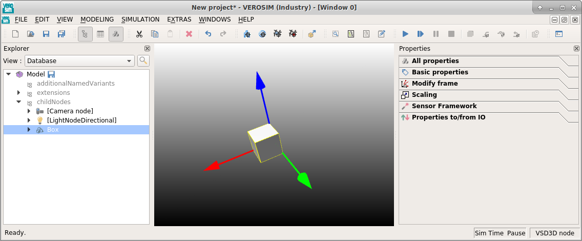
The Graphical User Interface
The user interface provides a number of graphical elements, which user can interact with:
- The
render windowin the center - The
menu barand thetoolbarat the top - Widgets, like the
Exploreror thePropertieswidget, at the sides
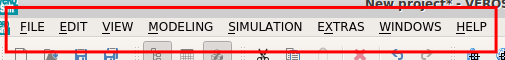
The Menu Bar
You will find a number of menus in the menu bar that contain a variety of actions.
The most important ones in the context of ReconCell are the File and Modeling menus. These menus contain actions that will be described in more detail in further sections of this user manual.
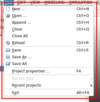
The File menu contains general controls to interact with projects and the models contained therein. The menu entries
- New
- Open
- Close
- Reload
- and Save
allow control over the current project. In addition, you can exit VEROSIM through the Exit action in this menu.
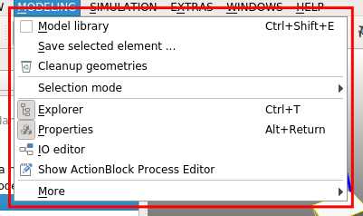
The second important menu is the Modeling menu. It provides access to useful tools like the Model Library, the IO Editor and the ActionBlock editor. All of these tools will be covered in detail in different sections of the user manual, so please refer to those for exact instructions on how to use them.
The Model Library
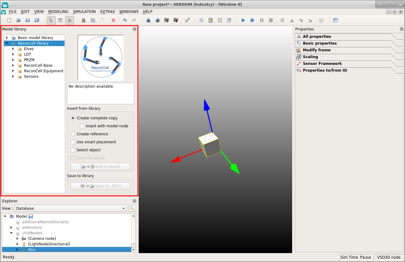
The following image shows the Model Library that contains a list of different libraries. All of them provide a number of models that can be inserted into the current model. The default setting appends a deep copy of the selected model, which is in most cases the behavior that you will need during the modeling of a robotic workcell. A click to Add to model will perform the copy and insert the selection into your current model. Please keep in mind that the use of the Model Library requires you to always append an element to an already saved model. Therefore, you should make sure to save your work before attempting to use the Model Library.
Activating GUI elements
The menu bar allows access to the different GUI elements. If one or another widget or toolbar is missing, you can simply navigate to the Windows menu where you will find a list of dockable widgets below the Dock widgets item or a list of toolbars below the Toolbars item.
Toolbars
You can use different tools that are available through the toolbar. By opening the context menu on the toolbars (right click) you can select which toolbars should be visible. So, if you miss a specific toolbar, you should check its visibility.

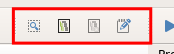
Throughout modeling tasks it is useful to select assemblies without navigating through the tree structure of the model. Therefore the selection toolbar provides functionality to select parts or assembly groups in the render window (center). Activate the selection mode and click on any graphical element inside the render window and it will be highlighted in the explorer window (see below).
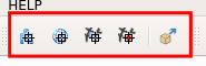
The ActionBlock toolbar provides a number of tools to visualize agents or targets that are linked to a specific (the currently selected) ActionBlock. This helps during the visual programming tasks as it provides visual feedback regarding which agents will operate or which targets will be interacted with during an action. In addition, this toolbar provides the controls to export the programmed sequence to SMACHA such that the physical workcell can be operated without the simulation system in the background.
The scheduler toolbar allows interaction with the execution of processes and simulation runs. A simulation or a process can be started by clicking Start simulation, or stopped by clicking Reset simulation. Additional actions provide the means to pause and progress the simulation by a specific amount of time.
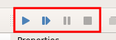
Each action provides a hint while hovering the mouse above a toolbar. This helps identifying which action to activate. The status bar provides the same information to help the user navigate through all the different and available actions. The toolbar also contains information about the simulation run. It indicates the current status (running, paused, stopped) and the current simulation time.

The Explorer Widget
The explorer widget contains a detailed view on your project. It contains a tree structure that represents all the different elements that your model comprises. All of these elements are selectable and provide access to the properties of the selected element. In some cases it is useful to navigate through the explorer to find specific elements. Sometimes and especially if the model is very large, it is helpful to search for the element that you are looking for. Just click on the magnifying glass and enter the name of the element that you are looking for. Once selected you will see details about the selected element in the property widget.
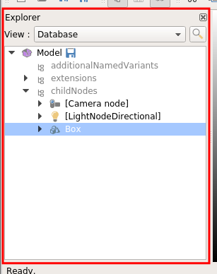
The explorer widget provides access to the simulation database (VSD) by providing a tree view on the whole data structure. Each branch represents a unique dataset that you can interact with. Branches are expandable, which means that you can open a dataset to access the datasets contained within. In addition, each element in the tree has a context menu that you can open by right clicking on the respective element. You will find a variety of actions that are specific to the selected element. Some basic tasks are usually performed by utilizing the context menu.
Rename an entry
Right-click the element you want to rename and select Rename entry in the context menu. Pressing F2 is the shortcut to use the rename functionality without using the context menu.
Append an element
The explorer provides two kinds of reference properties. A containment reference (also called auto delete ref) and a link reference (also called not auto delete ref). In addition both kinds of properties are available as a single reference or as a reference list.
By using the context menu in explorer you can assign references to these kind of properties. Depending on the kind of property, the context menu will provide entries to choose from: append or create elements. Adding elements to a containment reference will prompt a list for creating new elements: Context menu -> Append new element. Adding elements to a link reference will prompt a list of elements, that are already present in the VSD: Context menu -> Choose element.
These actions make the difference between containment and link references clearer. Containment references contain a reference to the instance that will live below the parent. When the parent is moved or deleted, the referenced instance will be moved or deleted accordingly. In contrast, the link references always refer to an element that lives somewhere else but needs to be accessed from the parent.
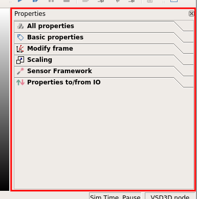
The Property Widget
The property widget contains details about a selected element. This could be the element’s name, visibility, or size (e.g. for the box). The view on an element’s property can be very general (All properties or Basic properties) or specific to the element’s semantics (e.g. Modify frame allows to change an element’s position and orientation by providing graphical feedback).